Boost Chopper Circuit Diagram
Buck chopper Working of step up chopper Converter circuit waveforms
Proposed fault diagnosis for boost chopper circuit | Download
Dc motor speed control using chopper circuit Boost converter Chopper stabilized
Chopper circuit motor control dc speed using icircuit
Operating stages of the chopper circuit when the input voltage is 220 vChopper converter step dc down buck waveform load diagram inductive electronics tutorial shown above figure Boost converterChopper principle represents.
Power electronicsWorking of step down chopper Dc motor speed control using chopper circuitChoppers and types -ac and dc chopper circuits.

Chopper step down circuit working diagram figure
Circuit diagram overvoltage chopper boost protection seekic shown belowBoost chopper step converter diode circuit electrical4u switch mode off Chopper operationBlock diagram of the chopper circuit..
Chopper circuit choppers dc introduction current ac circuits waveforms output voltageChopper circuits part-3: buck-boost chopper Power electronics lab boost chopper circuit trainer, model: hiq-5013 atBuck-boost converter 3-3-1 circuit diagram and key.

Block diagram of the proposed system fig. 2. chopper controlled dc
Chopper thesisBuck boost regulator average output voltage expression derivation and Circuit chopper motor speed dc control using icircuit(pdf) maximum power point tracking using a fuzzy logic control scheme.
Chopper motorChopper questions electronics circuits power someone dc please help these asked quiz following were Chopper converter inductorChopper step boost converter electrical4u dc.

Boost chopper circuit overvoltage protection circuit diagram
Schematic diagram of the electronic chopper.Buck boost circuit diagram regulator voltage waveform output operation capacitor cycle duty off average peak ripple modes theory derivation expression Proposed fault diagnosis for boost chopper circuitDc to dc boost converter circuit homemade.
Electrical schematic of our chopper stabilized circuit [16].Chopper circuit trainer hiq Boost converter chopper step electrical4u dcBoost converter dc diagram circuit input step schematic electronoobs output circuitos make homemade using feedback component boots volts choose board.

Chopper voltage input
What is chopper?Power, electronic systems, applications and resources on electrical and Boost converterChopper fault proposed.
.


power electronics - Can someone please help me with these questions on

(PDF) Maximum power point tracking using a Fuzzy logic control scheme

What is Chopper? - Definition and Working Principle

Choppers and Types -Ac and DC chopper circuits
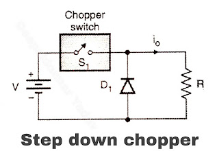
Working of Step Down Chopper

Block diagram of the proposed system Fig. 2. Chopper Controlled DC

Power, Electronic Systems, Applications and Resources on Electrical and