Binary Full Adder Circuit Diagram
Binary adder half and full adder Adder binary adders rtl discuss Adder bit subtractor binary verilog subtraction input numbers two addition operation values control has both
Solved 1. The figure above shows a 4-bit BCD adder. You can | Chegg.com
Full adder circuit diagram 6.4: 2-bit adder circuit Adder logic projectiot123 introduction binary carry sum outputs
Adder binary half parallel electrical4u
Adder binary circuitverseBinary adder circuit / circuit additionneur binaire Adder bcd bit binary two diagram logic block adders combinational figure answer shows solved has helpAdder adders libretexts circuits pageindex.
Full adder circuit: theory, truth table & constructionDigital logic design: full adder circuit 4 bit binary adderAdder binary parallel bit logic diagram circuit electronics between.

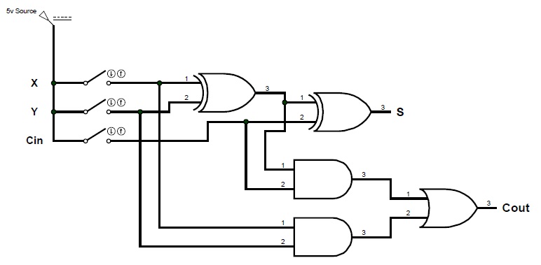
Binary adder and binary addition using ex-or gates
Full adderAdder cmos circuit diagram transistor fa 28t transistors implementation edacafe using transmission gate power fig phdthesis www10 book Adder logic binary circuit gates diagram using array inputs made twice labeled below also usedWhat is parallel binary adder?.
A binary adder made using and-or array logicTech2play: binary addition Alex9ufo 聰明人求知心切: verilog 4-bit binary adder-subtractorFull-adder circuit, the schematic diagram and how it works – deeptronic.

Circuit adder bit logic ece generate truth table now diagram number
Adder bit circuit subtractor ripple carry logic diagram using project only digital its computing learn let build single indie electronicsAdder circuit electronics outputs 13+ full adder block diagramAdder circuit diagram schematic bit works figure.
Edacafe: power, accuracy and noise aspects in cmos mixed-signalAdder subtractor logic combinational sub binary subtraction adders Adder half arithmetic circuitsAdder additionneur binaire zpag electroniques gate sum.

Adder circuit combinational ha sequential
Adder binary bit addition carry python will using bits gates input combination program sign rippleHalf adder logic diagram and truth table / obe assignment: digital Ece logic circuitFull adder circuit diagram.
Let's learn computing: 4 bit adder/subtractor circuitAdder xor rangkaian transistor ripple pengertian kombinasi Circuitverse adderBinary arithmetic circuits.
Adder sum implementation logic combinational circuits simplified
Solved 1. the figure above shows a 4-bit bcd adder. you canAdder circuit construction binary circuits qiskit sourav gupta Adder circuit binary logic output xor boolean electronics diagrams derivedBinary adder/subtractor.
Adder diagram binary additionCombinational and sequential design of a 4-bit adder. (a) ha circuit Adder circuit logic using boolean digital function diagram implementation implement.


Full Adder | Electronics Tutorial

Half Adder Logic Diagram And Truth Table / OBE Assignment: Digital

Binary adder circuit / Circuit additionneur binaire

Binary Adder Half and Full Adder | Electrical4U

Full-Adder Circuit, The Schematic Diagram and How It Works – Deeptronic

Full Adder Circuit Diagram

tech2play: Binary Addition